 Loop
Loop Materials
LACE: fibre path planning software for LOOP
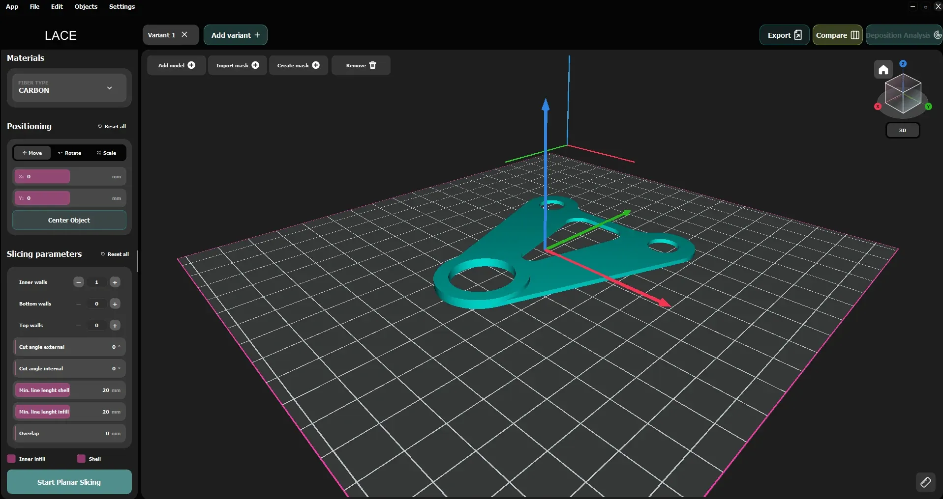
LACE is the fibre path planning software developed by Spherecube and the first step in automated manufacturing with LOOP. It takes a 3D model, works out where the fibre should run and writes the program for automated deposition, on the table or on the mandrel. Choose how to lay the fibre, watch it build up layer by layer and produce only when you are sure.
Infill other software doesn't offer
Each infill goes where it works best. The fibre runs in stretches of at least 20 mm and changes direction in smooth curves, never at a sharp corner. Fibre orientation optimisation is in your hands: you choose the angle layer by layer, 0°, 90°, ±θ or steered paths and LACE turns it into a path that LOOP can lay without wrinkles.
More than one infill in one part
Mark a zone of the part with a mask and give it its own infill, for example around a hole. Outside the mask, the part stays as it is. Unlike composite CAM software or AFP path planning tools that apply a single pattern to the whole part, LACE lets you mix infill, walls and directions in the same component.
- Import the mask as a file or create it in LACE.
- It has its own settings: infill, walls, direction.
- The rest of the part is left untouched.
The mandrel fills up without gaps
- Constant pitch or constant angle, layer by layer.
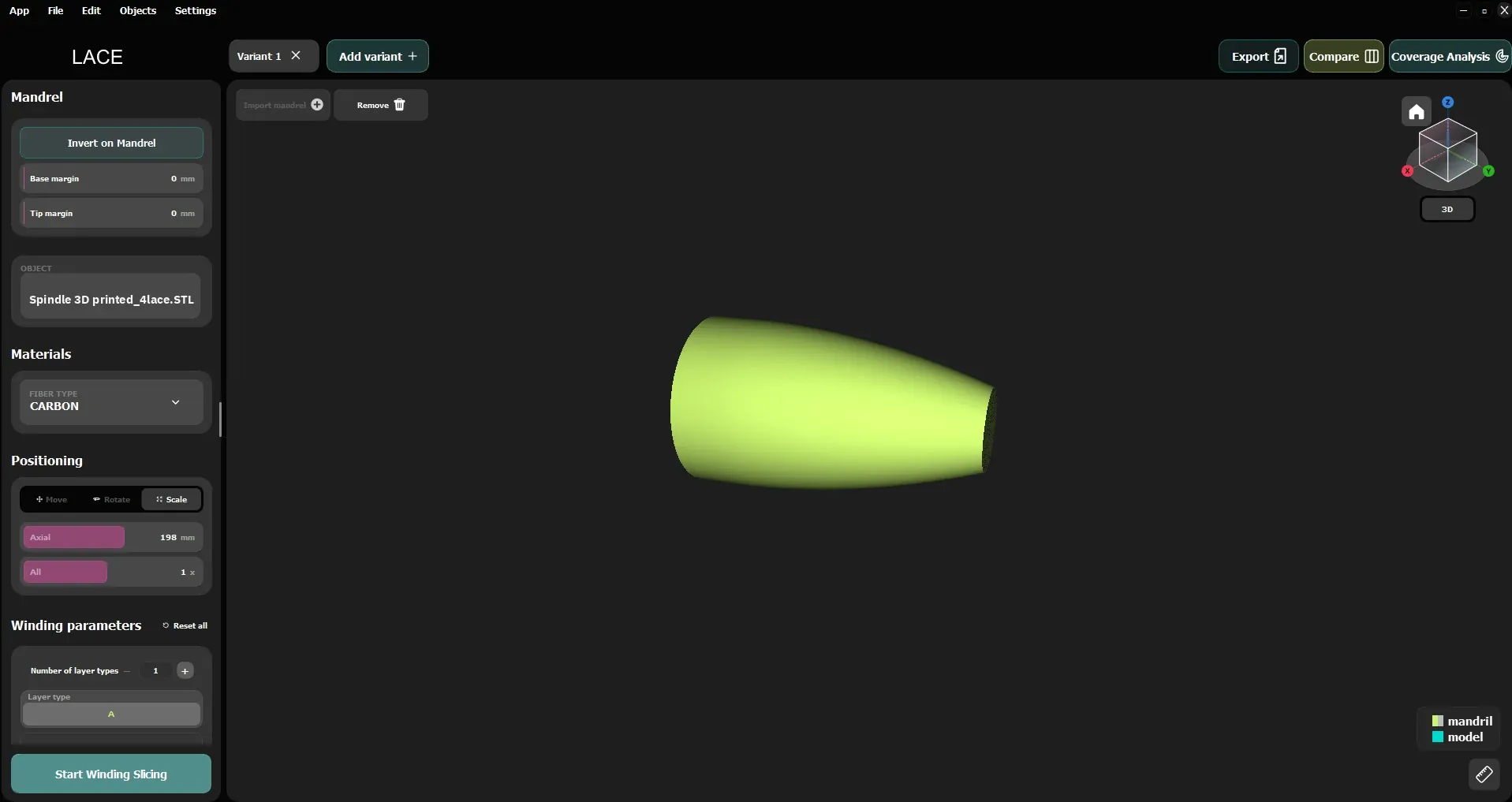
- The fibre is cut and restarted where needed to close the gaps, with constant pitch or constant angle. Compared with classic filament winding, where the fibre never stops and follows a helix at a fixed angle, here you choose the angle and coverage builds up layer by layer.
- Recipe-based layers, up to the thickness you want.
- Before production, LACE tells you whether coverage is complete.
Compare variants before you produce
Which variant is worth building? With LACE you keep several versions of the same part side by side and compare them by weight, cost and time. Pick one on screen, before anything goes to the machine, rather than through trials on the shop floor.
Indicative values, for illustration.